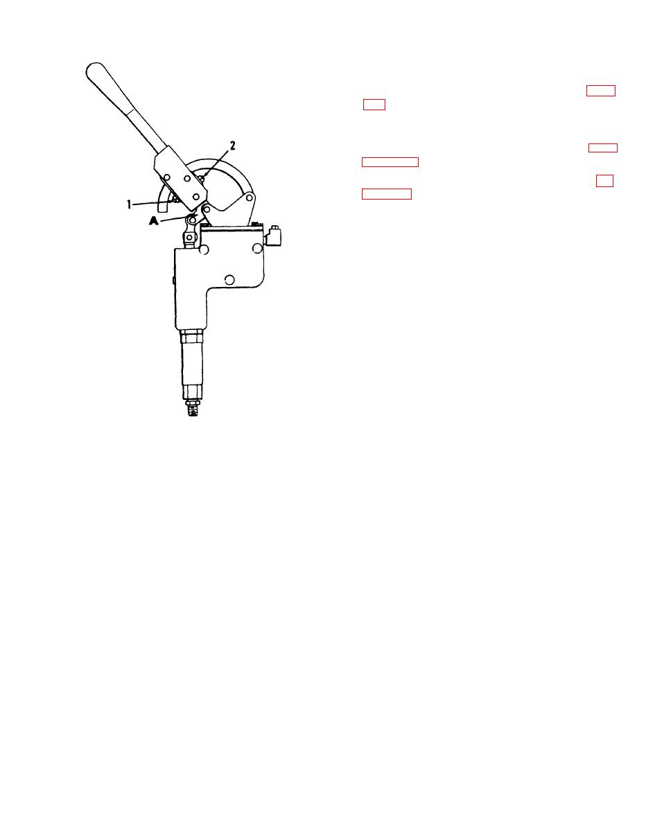
(4) Set both jam nuts on set screws (1
and 2).
(5) Fill and bleed hydraulic system (para
6-14. Relief Valve
reassemble the relief valve.
c. Cleaning, Inspection, and Repair.
(1) Clean parts with an approved cleaning
solvent and dry thoroughly.
(2) Inspect parts for cracks, breaks, or
other damage. Replace any defective parts.
MEC 3895-265-15/43
Transmitter handle adjustment.
Figure 6-13.
6-13
AGO 20049A


